

Inquiry question 5:
How is CAD a beneficial tool for designing and engineering solutions?
6.1 Electronics
Students learn about:
- practical applications
Students learn to:
- Develop prototypes using a variety of materials to simulate motion produce models in order to solve problems related to motion
Lessons 13, 14 & 15:
 Student Design Challenge: Designs have progressed to a stage where they can be documented formally and in detail. These lessons also present opportunities for modelling the design. There are two types of drawing and modelling here:
- For the body of the Kombi
and - For the circuit.
Process for drawing and modelling the Body of the Kombi: Teacher demonstration: presentation of final designs on CAD including dimensioning.
Video 5.15.1: The Engineering And Technology Design Process The benefits of using CAD in STEM projects through an example with the Kombi project.
 Student activities (conducted in TinkerCAD or using isometric hand-drawings):
- Design is drawn in 3D.
- Design is presented assembled as a 2D orthogonal drawing with dimensions.
- Students to document final design templates in CAD.
- Drawings must be fully dimensioned!
Process for drawing and modelling the Circuit:
Teacher demonstration: Teacher models the use of CAD application of choice or TinkerCAD to demonstrate common components or those useful to the design task:
- Demonstrate component library
- Assembly of circuit
- Simulation of circuit
- Manipulation of components, or change of component values
Student activities:
- Students practise electronics knowledge and skills development through simulating circuits on TinkerCAD.
- Students to simulate the function of the circuit using the TinkerCAD simulator.
- Students to evaluate efficacy of circuit to create motion. Students to work on circuit refinement in TinkerCAD until desired outcome is simulated. This can be achieved using the multimeter to check amperage and suitable resistors.
Resources
CAD of choice
Video 5.15.1: The Engineering And Technology Design Process Engineering Student Max Den Exter from Southern Cross University highlights the benefits of using CAD in STEM design work
(start @ 2:25min)
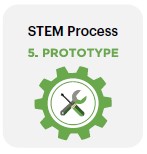
Example: Part of a 3D model in SketchUp
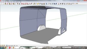
Example of a 2D orthogonal drawing with dimensions

Resources for drawing and modelling the Circuit:
Teacher demonstration: Use the following components:
- Multimeter
- Motor
- LED
- Resistor and potentiometer
- 3V or 9V battery